Assembling of the main board for Jasmine III
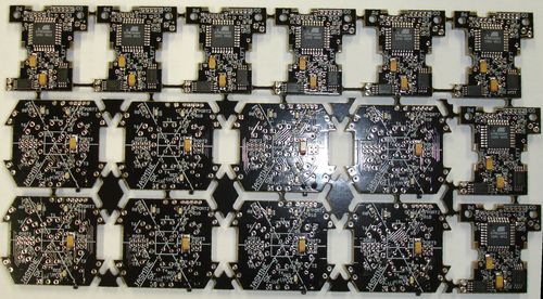
The main and motor board are provided in the form of a so-called "Nutzen" - 8+8 boards in the euro-PCB format. You can divide the "Nutzen" into separate boards just at the beginning, or (recomended) after step 3.
The thickness of the PCB is 1.5 mm and they are painted black - this is important for optical isolation. They are completely SMD-assembled, however without large components like emitters/receivers and without the bootloader in the microcontroller's flash.
1. Step. Upload bootloader to flash.
For this you need any In-System Programmer, for example AVRISP
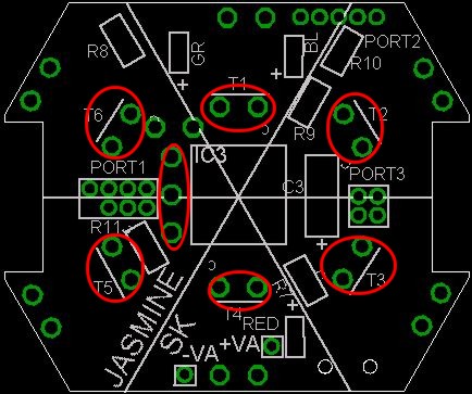
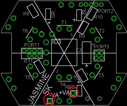
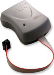 . The ISP connectors on the boards are shown below.
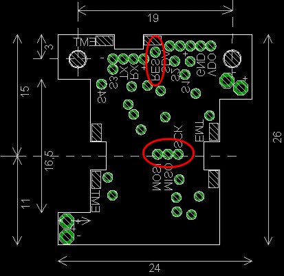
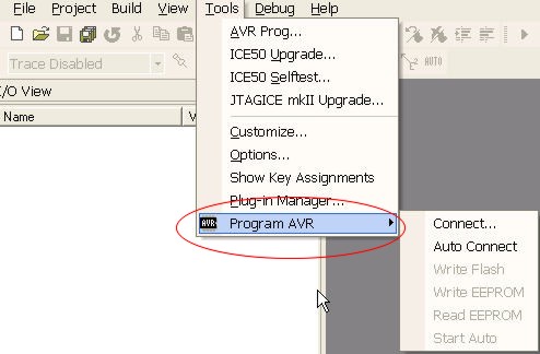
Start AVR Studio, connect ISP programmer and call the corresponding menu:
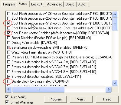
Program the fuses first (BE EXTREMELY CAREFUL WITH PROGRAMMING FUSES - DO NOT CHANGE ANY OTHER SETTINGS):
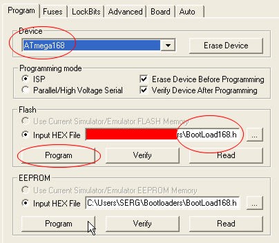
Put bootloader into flash (ATMega168 for the main board and ATMega88 for the motors board). Bootloader can be found in the section "Software".
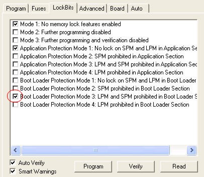
Optionally, you can protect the bootloader
After this step, test the bootloader by writing some program into microcontroller. The known bug now - some microcontrollers do not load programs at 3V (they need about 3.3V). Another known bug - sometimes the bootloader can later be destroyed by several reasons - then you need to upload the bootloader again.
2. Step. Soldering large components on the main board.
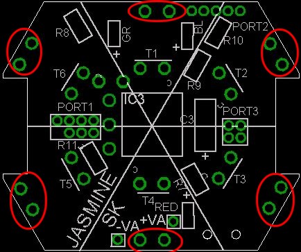
2.1. Firstly solder the remote control sensor and receivers on the top side of the main board. Be careful with emiter/collector legs of emitters (C is for collector). CHECK this many times before you solder -> it it very difficult to resolder due to thickness of PCB
.jpg)
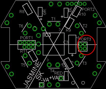
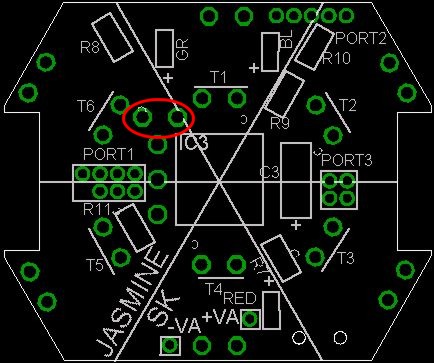
2.2. You receive 2x10 connectors
 . Divide them into two parts: 2x4 and 2x2. Solder connectors on the top side.
2.3. Solder emitters on the bottom side of the main board
.jpg)
2.4. Grind the beamer TSAL6100 from both sides so that the thickness will be about 2mm (you can see parabilic mirror in the beamer). Do not damage this mirror and the front surface of the beamer. Solder this emitter on the bottom side of the main board. Be careful with "polarity" of the emitter (C -cathode).
.jpg)
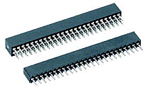
3. Step. Close all open vias in the main board. Close all open vias (holes) by soldering, so that no IR light can come from the top side to the bottom side (this is very important !).
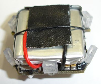
4. Step. Installing accu. Solder wires to accu (red "+", black "-") by wire 0.1-0.15 (not thiner)
Finally, place the accu with the glued power management board in the main board, solder the contact, isolate and fix by thin wire.
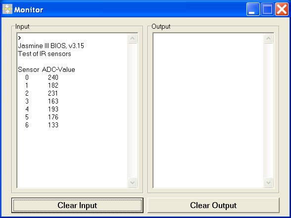
5. Test the sensing system. Write into flash the program JasmineSensorsTest.hex. The on-board LED should flicker one time. The program tests the sensors. The ADC values without any reflecting objects should be no larger than 3-5,
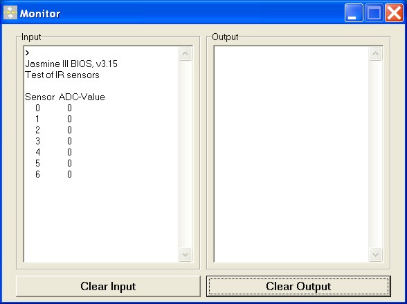
with reflecting objects - up to 255.
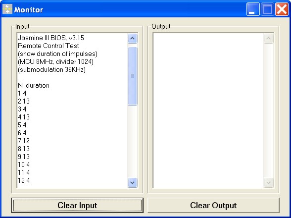
6. Test the remote control. Write into flash the program jasmineRemoteControl.hex. The program prints the duration of PCM impulses, received from the remote control. These durations can used for programming customized remote control.
With this step the assembling of the main board is finished.