Questions to TWI Interface
For intermodular communication, TWI is the most suitable - only two lines. Therefore it seems important to put some preliminary consideration on TWI.
-
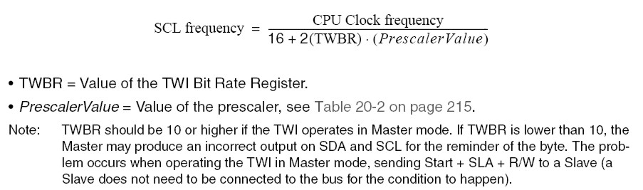
CPU clock frequency of Slave should be at least 16 times higher than SCL frequency
- SCL frequency is calculated by the following formula
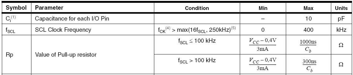
The pull-up resistors can be calculated from the bus capacity <50 pF, F>100kHz and Vcc=3V -> they are between 800 Om-6K. In the main board they are 2k on each channel.
TWSR&=0b11111100; // prescaler value =1
TWBR= 0b00001011; // SCL = 8000000/(16+2*TWBR)*(Prescaler) => 8000000/(16+2*11) =>210526 Hz TWI interface
This is almost maximal SCL frequency achivable at 8 Mhz. It works quite stable at this frequency. TWI is used in multi-master mode with arbitration. It requires a lot of code, but also work more or less stable (still testing now).
- TWBR=(10..15);
- General call is enable
- Slave adress 1 is the main board
- Slave adress 2 is the motion board
- Slave adress 3 is the GPS board
Transmission on TWI bus is in the following format: the last byte is alsways command. The command can have N arguments which should be sent before. General number of bytes is not limited ... however make as small as possible each sent byte means additional effort for processing. For SCL frequency 200 kHz, sending of two bytes (adress + 1 data byte) + start-stop-ask bits (=20 bits) takes 0,1 ms.
- All extention boards have a small delay in initializtation procedures so that the main board gets initialiazed as the first one
- All extention boards during initialization send to the main board one byte with their identification code. In this way robot knows its own configuration.
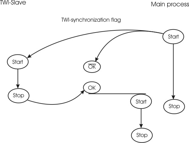
The master process (usual timing ms) is much quicker than the TWI-slave process (usual timing s), therefore they have to be synchronized. This synchronization is done by using TWI-synchronization flag (bit 6 of mainStatus). Starting, the main process has to clear this flag. When the slave process is finished it has to set the flag.
TWI commands can be transmitted by the command SendTWI(adress,1st byte, 2nd byte). Zero instead of argument means that this byte will be not transmitted (e.g. SendTWI(1, 1,0) ).
TWI commands of the motion board (slave adress 2)
| Numerical code | N of bytes | description | |
| 1 | 1 | Stop motion. Motion board goes into idle mode (to save energy). | |
| 2 | 1 | Continuos motion. Robot moves till the main board stops it. | |
| 3 | 2 | Move in a distance defined in the argument (the second byte). | |
| 4 | 2 | RotateLeft(), the second byte is rotation degree (0-255/10). | |
| 5 | 2 | RotateRight(), the second byte is rotation degree (0-255/10). | |
| 7 | 2 | Set motion velocity (0-127 rev.; 128-256 forw.; 0 and 255 are max.) transmitted by the second byte | |
| 8 | 2 | Set the touch threshold transmitted by the second byte | |
| 9 | 1 | Start checking touch sensor | |
| 10 | 1 | Stop checking touch sensor (default value) | |
| 11 | 1 | Give sensor value from touch sensor | |
| 12 | 1 | Give sensor value from energy sensor | |
| 13 | 1 | Start using odometry | |
| 14 | 1 | Stop using odometry | |
| 15 | 1 | Give sensor value from S1 input | |
TWI commands of the main board (slave adress 2)
| Numerical code | N of bytes | description | |
| 1 | 1 | Set TWI synchronization flag. | |
| 2 | 1 | Motion board configuration (motion board is present and working). Answer: 2. | |
| 3 | 1 | "low energy" (3.3V) | |
| 4 | 1 | "critical low energy" (3.1V) | |
| 5 | 1 | Touch contact established. It is sent only one time when first contact | |
| 6 | 1 | Touch contact lost. It is sent only one time | |
| 7 | 2 | Receive value from the touch sensor (in the second byte) | |
| 8 | 2 | Receive value from the energy sensor (in the second byte) | |
| 9 | 2 | Receive value from the S1 sensor (in the second byte) | |
| 10 | 2 | activate LED_play | |
| 11 | 2 | Receive value from the S2 sensor (in the second byte) | |
| 12 | 2 | Receive color value from color sensor (in the second byte) | |
| 13 | 5 | Receive position (Byte 2: high Byte position x(Bit 0,1), y(Bit 2,3), theta (Bit 4,5) | |
| Byte 3: low byte x, Byte 4: low byte y, Byte 5: low byte theta) | |||
| 14 | 3 | Receive data (Byte 2: highByte data, Byte 3: low byte data) | |
| 15 | 3 | Receive pheromone (Byte 2: left sensor, Byte 3: right sensor) | |
TWI commands of the ODeM board (slave adress 3)
The first six commands are equal to the commands of the motor board. The idea behind this is that the motor board brodcasts this commands. Those commands could than be used by a kalman filter to improve the position estimate. This could be signifficantly important when measuring the position while moving.
| Numerical code | N of bytes | description | reply |
| 1 | 1 | Stop motion. Motion board goes into idle mode (to save energy). | no reply |
| 2 | 1 | Continuos motion. Robot moves till the main board stops it. | no reply |
| 3 | 2 | Move in a distance defined in the argument (the second byte). | no reply |
| 4 | 2 | RotateLeft(), the second byte is rotation degree (0-255/10). | no reply |
| 5 | 2 | RotateRight(), the second byte is rotation degree (0-255/10). | no reply |
| 7 | 2 | Set motion velocity (0-127 rev.; 128-256 forw.; 0 and 255 are max.) transmitted by the second byte | no reply |
| 8 | 2 | set/unset continous position measurement bit (1/0) | no reply |
| 9 | 2 | set/unset continous data measurement bit (1/0) | no reply |
| 10 | 2 | set/unset continous pheromone measurement bit (1/0) | no reply |
| 11 | 2 | measure now 1: postion, 2: pheromone, 3: data | 1->13, 2->15, 3->14 |
| 12 | 2 | measure the absolute pheromone value. The second byte defines the number of measurements from which the mean ist calculated | 15 |
| 14 | 2 | turn on/off status led 1 RED (1/0) | no reply |
| 15 | 2 | turn on/off status led 2 BLUE (1/0) | no reply |
| 16 | 2 | turn on/off status led 3 YELLOW (1/0) | no reply |
| 17 | 2 | turn on/off super bright led 1 (1/0) | no reply |
| 18 | 2 | turn on/off super bright led 2 (1/0) | no reply |
| 19 | 2 | turn on/off super bright led 3 (1/0) | no reply |
| 20 | 2 | turn on/off super bright led 4 (1/0) | no reply |