Assembling and calibrating the robots vIII+
To start assembling the robots vIII+ you need to have the following already assembled and tested (!!!) components:
1 Power Management Board, glued on the accu.
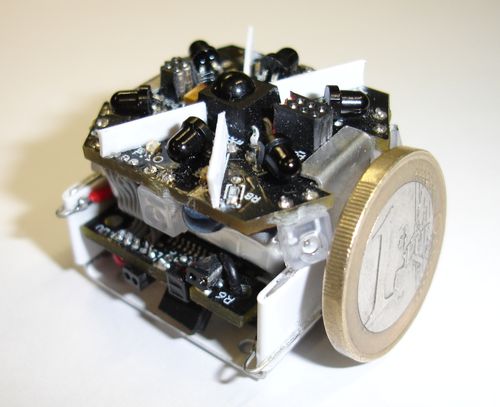
2 The main board with the integrated accu (and the power management board).
.jpg)
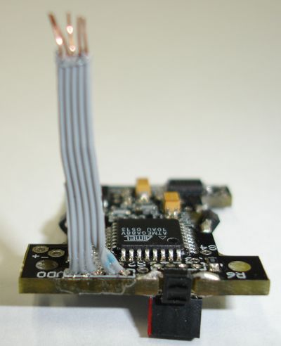
3 The MotorsBoard with the serial connector, TWI BUS and all sensors.
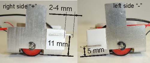
4 The assembled chassis (gear + wheel + axis + spring + wishers) with the glued front contacts and white painted (!) front part.
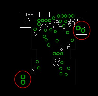
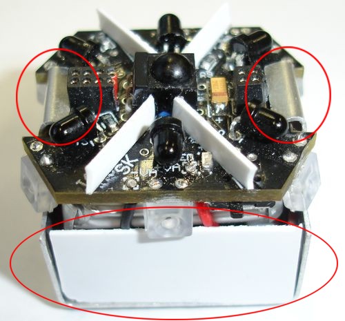
Make sure that the front connectors correspond to this specification
All boards should be tested with the corresponding test programs (!!!).
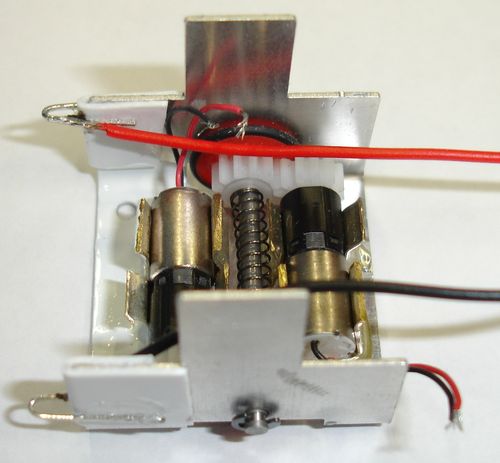
Step 1. Solder the motors' wires to the MotorsBoard. Solder these wires (each motor has one red "+" and one black "-" wires) from bottom to the MotorsBoard. Be sure, that there is no shortcut between "+" and "-" (other case the H-bridge burns out).
Step 2. Glue the MotorsBoard on the motors This step is extremelly important for working of odometrical system. Please execute all next steps as precisely as possible.
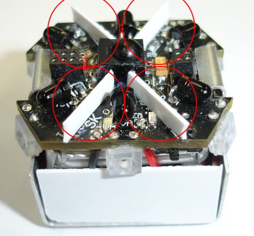
2.1. Lay down the MotorsBoard on the motors. Be sure that board lays really on motors and not on the motor holders (fuses). When required, cup out a part of the motor holders. The distance between each odometrical sensor and the corresponding gear should be about 1mm. Sensors should not touch the gears (!) and should be not far away from the gears (!).
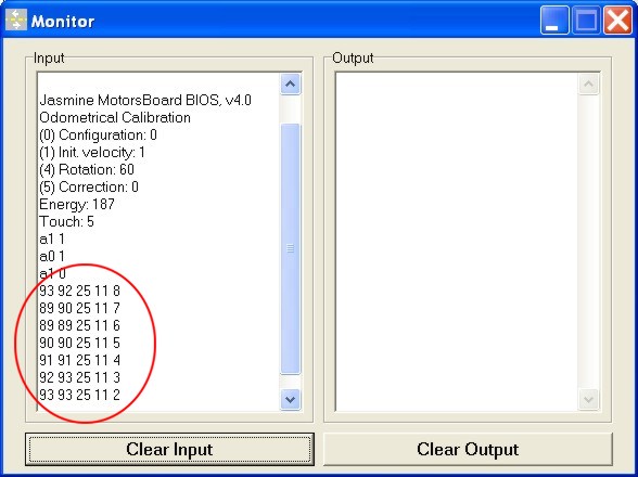
2.2. Write into flash the program jasmineMB_OdomTest.h. Hold the board in the correct position with a finger (do not glue it first) and put the voltage to the board (V+, VDD and GND, V+ and VDD can be connected). Motors shold start rotate, you will see the following information:
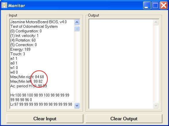
Make sure that the difference between Max and Min in both weels is more than 15 (!!!). When difference in smaller, put sensors closely to gears (resolder the upper legs and incline the sensor more to the gear). Shift board to make Max in both wheels more or less equal.
2.3. Make sure that the "w " command appears always with different parameters and the periods are more or less similar. When not, put sensors closely to gears
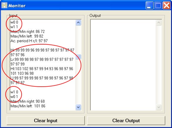
2.4. Now glue the MotorsBoard in the position that you fixed by finger. We suggest using a "plastic" glue (not a glass like acryl "second glue"), for example used for glueing plastic materials. Repeate the steps 2.2-2.3 to find the best position of the MotorsBoard. Let the glue dry (!).
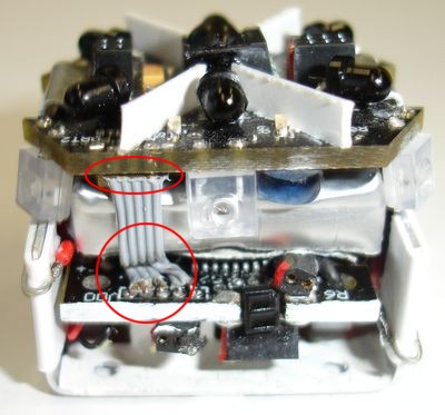
Step 3. Solder the TWI bus. Put the TWI Bus into the corresponding connectors on the main board the solder it.
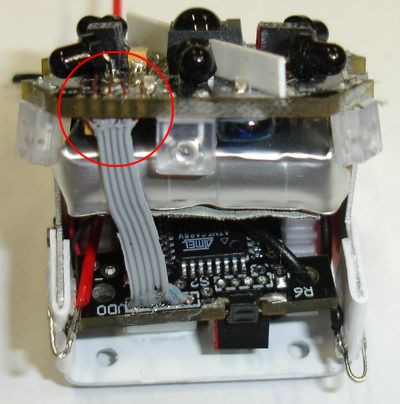
Folder the cable like shown below:
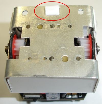
Step 4. Bend the chassis to fix the main board and glue the plastic elements. Bend the chassis to that to fix the main board.
Glue the back (white spastic part) to the MotorsBoard (can be done with a "glass" like glue, like acryl "second glue"). Glue the optical isolation (when it is not glued before)
Glue the passive wheel (the best from teflon-like material with minimal friction).
Step 5. Calibration of the velocities. Write into flash of the MotorsBoard the program jasmineMB_Calibration.hex (Make sure, that you also wrote the jasmineMain.hex into the flash of the main board). Lie the robot on the back (so that it does not move) and push "Start" on the remote control.
This program calibrates three velocities on the robots and automatically finishs when they are calibrated. Make sure that you see changing of velocities coefficients and hear different sound from the motors. Calibration should not take more than 2-3 minutes (other case motors gets warm and at the cold start the robot will move aslant till odometry corrects this). When it took too long time, swith off the robot and after 5-10 minutes repeate the calibration.
Step 6. Final calibration of the robot. Write into flash of the MotorsBoard the program jasmineMB_Main.hex. This is the final BIOS program that works thogether with the main board BIOS. The robot is manually assembled, it means that all robots are different in mechanical parameters, like motor-wheels coupling, friction and so on. Therefore you need to put manual correction coefficient, that is unique for each robot.
6.1. Let the robot move about 3-5 minutes. When the calibration was OK, robot will moves more or less directly. Odometrical system take care about direct motion (both wheels gone the same distance), for this robot should first move about 20-30sec. witnout collisions.
6.2. After 3-5 minutes, take a look at the motion trajectory of the robot. When it is not a direct line, change the correction coefficient. For this switch off the robot and within 1 sec after swith on, write "0" into the OUTPUT window. You will see the EEPROM update routine:
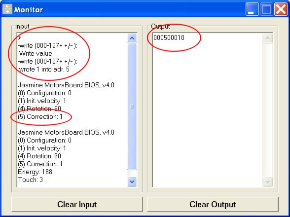
Write first the EEPROM adress in the form "0050" and after that write the correction coefficient in the form "0xx0" for positive coefficients or "0xx-" for negative coefficients (e.g. coefficient "10" means "0100", coefficient "1" means "0010", coefficient "-1" means "001-"). When input was correct, you will see the correction coefficient in the configuration.
Usually the robot cut more on the right side (it moves right circles), it requires a positive correction coefficient between 1 and 5.
6.3. Leave the robot moves again about 3-5 minutes. When it moves still not directly, change the correction coefficient. When the correction is finished, start the velocities calibration again so that put this coefficient into all velocities.
Congratulation, you finished assembiling of the Jasmine VIII+ robot. Good luck with your swarm robotics experiments