Power management board
Lithium Polymer (LiPoly) is the most likely battery chemistry choice for small robots due to its high energy density and output current capabilities. LiPoly? cells can be dangerous if not treated properly, however. A safe LiPoly? cell needs to be protected against overvoltage, undervoltage, and overcurrent to prevent damage to the cell, overheating, and possibly fire.
Supporting a large robot swarm would be difficult if each robot required manual recharging. Therefore, a mechanism that allows a robot to automatically dock with a charging station is desired. Finding and engaging with a charging station is a higher level task than should be handled by just the power module, however, the power module should contain the necessary recharging contacts and make engagement as easy as possible.
Additionally, if the power module already has recharging contacts, it makes sense to include a couple more contacts for hi-speed bidirectional communication between a bot and host computer while recharging.
LiPoly? requires careful management to insure safety and cell health. Two management modes are required: Charging, and discharging. Obviously, the discharge management circuitry must reside in the bot. The charging management circuitry may be located off of the bot, but does it make sense to do so?
It is important to charge LiPoly? batteries correctly to prevent damaging the cells, or worse, causing a fire. Charging typically consists of a period of constant current (1C) until the battery voltage reaches a threshold, and then a period of constant voltage (4.2V) until current drops below a certain threshold (1/10C). Additionally, if the battery is below the trickle-charge threshold voltage (2.9V) at the start of the charge, it should be charged at a low rate (1/10C) until the trickle-charge threshold has been reached.
A number of integrated charging solutions exist for LiPoly? batteries. With a single IC and a couple of external passive components, a LiPoly? cell can be safely charged with a simple 5V input. IC's are usually designed for a specific number of cells, and charge current is set by an external resistor. Charge termination is determined by either time, or preferably by detecting when charge current falls below C/10. Some IC's also include thermal monitoring to insure battery temperature remains safe.
Possible charge management IC's:
Linear Technologies
LTC4054-4.2
http://www.linear.com/pc/productDetail.do?navId=H0,C1,C1003,C1037,C1078,C1088,P2294
Intersil
ISL6298
Microchip
National Semiconductor
Few selections. None w/ integrated FET?
Maxim
LiPoly? batteries can be damaged, or worse, catch fire, if they are shorted or discharged too quickly. Batteries may also be damaged if discharged below ~2.7V. Therefore, discharge management circuitry is necessary to insure safety and battery life. It may also be desirable to allow the bot to be powered from an external source, which requires power path management - either a simple switch, or automatic electronic switching.
Possible power-path control ICs:
Linear Technologies
LTC4412ES6
http://www.linear.com/pc/productDetail.do?navId=H0,C1,C1003,C1142,C1079,P2220
Possible discharge management ICs:
Texas Instruments
UCC3942-2
http://focus.ti.com/docs/prod/folders/print/ucc3952-2.html
A single integrated solution, if reasonably priced, may provide the cheapest solution.
Possible charge/discharge management ICs:
Texas Instruments
BQ24030
http://focus.ti.com/docs/prod/folders/print/bq24030.html
When in use, the bot must know when the battery is about to run out so that the bot can gracefully shutdown, or preferably, find a charging station to recharge itself. The bot's main controller could monitor the battery voltage directly, however, it would be preferable for the battery management circuitry to inform the controller of the battery's status. This would allow for different battery technologies to be used, where the low-battery voltage may vary, and would allow the controller to know more information about the battery, such as when it is being charged.
Communication can be accomplished over I2C, if the smarts are added to the battery management circuitry. A more evolved solution may be to use the System Management Bus (SMBus) protocol, which was developed for just this sort of thing. SMBus was initiated by Intel for smart batteries and other laptop system management functions, and is now a standard. See http://smbus.org/ This topic needs more investigation - it's likely that SMBus involves more overhead than desired.
The scheme of the power management module is shown below.
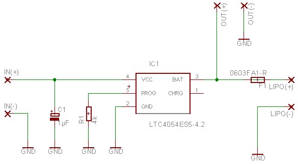
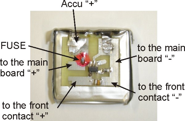
It uses LTC4054-4.2 chip. Please take into account the fuse 1A. It prevents destroying the LiPo accu (and the whole robot). The PCB of the power management board:
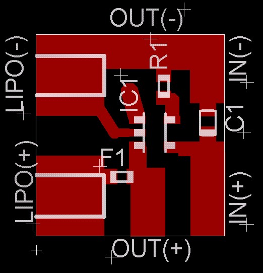
The position of the fuse is marked by red on the PCB
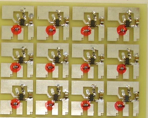
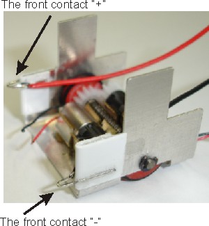
The board is glued directly on the accu, connections are shown in the following image
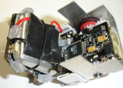
Finally the accu and board are installed on the main boards and soldered with power lines of the main board and with front contacts.
The eagle data of the power management board can be downloaded form the section "Documentation".
Supporting a large robot swarm would be difficult if each robot required manual recharging. Therefore, a mechanism that allows a robot to automatically dock with a charging station is desired. Finding and engaging with a charging station is a higher level task than should be handled by just the power module, however, the power module should contain the necessary recharging contacts and make engagement as easy as possible.
Additionally, if the power module already has recharging contacts, it makes sense to include a couple more contacts for hi-speed bidirectional communication between a bot and host computer while recharging.
Feature | Must have | Nice to have | To consider
|
| *Power source for bot | |||
| --Single ~250mAH Li-Poly? cell | |||
| *Battery management circuitry | |||
| --Charge management | |||
| --Safety management | |||
| *Soft power switch | |||
| --Allows for automatically powering down all bots with a remote command from the controller board (via I2C), or a button on the bot | |||
| --Allows for powering up or down a bot at a maintenance station via I2C commands | |||
| --A small reed switch could be used, which would allow multiple robots to be powered up or down by passing a magnet over the group | |||
| *Hard power switch | |||
| --Used for long-term storage or transport | |||
| --A simple slide switch in series with the battery | |||
| --Internal contacts that may be separated via an insulating plug inserted into small slot | |||
| ---Allows for easy packing of robots into a tray which has protrusions that fit into the power slots. These protrusions would automatically cut power to the robot and thus make it safe for storage or shipping. | |||
| ---For individual bot power-down or storage, a small plug could be inserted into the slot | |||
| *Contacts for power and communication to docking station | |||
| --Spring loaded for mechanical compliance | |||
| --Gold plated to insure good contact and minimize corrosion | |||
| *I2C interface for communication with controller board | |||
| --Battery status | |||
| --Soft-power control | |||
| --Link to external I2C interface | |||
| *I2C interface to docking station | |||
| --Battery management | |||
| --Bot power down/up, reset | |||
| --Link to rest of bot | |||
| ---Reprogramming of each microcontroller | |||
| ---Data transfer | |||
| ---Control |
LiPoly? requires careful management to insure safety and cell health. Two management modes are required: Charging, and discharging. Obviously, the discharge management circuitry must reside in the bot. The charging management circuitry may be located off of the bot, but does it make sense to do so?
Charging management located off bot
| |||
Advantages | Disadvantages
| ||
| *Reduce component count of bot | *Special charging station required | ||
| *Reduce price of bot | *Safety concerns if somebody tries to use an alternative charging method | ||
| *Requires separate sense lines for voltage monitoring (due to I2R losses in connector) | |||
Charging management located on bot
| |||
Advantages | Disadvantages
| ||
| *Charging only requires a fixed-voltage (5V?) source | *Increased bot cost | ||
| *Safety insured | *Increased component count on bot | ||
| *Support different battery technologies/# of cells with same charging station (may need to use higher than 5V though) | |||
| *Power bot off of external source and charge batteries with a single connector | |||
| *Allows monitoring of battery temperature by charging circuitry | |||
| *Allows for possibility of bots charging other bots | |||
It is important to charge LiPoly? batteries correctly to prevent damaging the cells, or worse, causing a fire. Charging typically consists of a period of constant current (1C) until the battery voltage reaches a threshold, and then a period of constant voltage (4.2V) until current drops below a certain threshold (1/10C). Additionally, if the battery is below the trickle-charge threshold voltage (2.9V) at the start of the charge, it should be charged at a low rate (1/10C) until the trickle-charge threshold has been reached.
A number of integrated charging solutions exist for LiPoly? batteries. With a single IC and a couple of external passive components, a LiPoly? cell can be safely charged with a simple 5V input. IC's are usually designed for a specific number of cells, and charge current is set by an external resistor. Charge termination is determined by either time, or preferably by detecting when charge current falls below C/10. Some IC's also include thermal monitoring to insure battery temperature remains safe.
Possible charge management IC's:
Linear Technologies
LTC4054-4.2
http://www.linear.com/pc/productDetail.do?navId=H0,C1,C1003,C1037,C1078,C1088,P2294
- Preset 4.2V Charge Voltage with ±1% Accuracy
- Programmable Charge Current to 800mA
- Constant-Current/Constant-Voltage Operation with Thermal Regulation to Maximize Charge Rate Without Risk of Overheating
- C/10 Charge Termination
- 2.9V Trickle Charge Threshold
- Automatic Recharge
- Charge Status Output Pin
- 25uA Supply Current in Shutdown
- Available in 5-Lead SOT-23 Package
- $1.76 (qty 100) (USD)
Intersil
ISL6298
Microchip
National Semiconductor
Few selections. None w/ integrated FET?
Maxim
LiPoly? batteries can be damaged, or worse, catch fire, if they are shorted or discharged too quickly. Batteries may also be damaged if discharged below ~2.7V. Therefore, discharge management circuitry is necessary to insure safety and battery life. It may also be desirable to allow the bot to be powered from an external source, which requires power path management - either a simple switch, or automatic electronic switching.
Possible power-path control ICs:
Linear Technologies
LTC4412ES6
http://www.linear.com/pc/productDetail.do?navId=H0,C1,C1003,C1142,C1079,P2220
- Only provides power-path switching - does not provide battery discharge management functions.
- Essentially, an ideal-diode
- Requires external pass-FET
- $1.54 (qty 100) (USD)
Possible discharge management ICs:
Texas Instruments
UCC3942-2
http://focus.ti.com/docs/prod/folders/print/ucc3952-2.html
- Precision Trimmed Overcharge and Overdischarge Voltage Limits
- Overcurrent and Short-Circuit? Protection
- Reverse Charger Protection
- Thermal Protection
- 3-A Current Capacity
- $2.45 (qty 100) (USD)
A single integrated solution, if reasonably priced, may provide the cheapest solution.
Possible charge/discharge management ICs:
Texas Instruments
BQ24030
http://focus.ti.com/docs/prod/folders/print/bq24030.html
- Integrated Dynamic Power-Path? Management (DPPM) Feature Allowing the AC Adapter or the USB Port to Simultaneously Power the System and Charge the Battery
- Power Supplement Mode Allows Battery to Supplement the USB or AC Input Current
- Autonomous Power Source Selection (AC Adapter or USB)
- Supports Up to 2-A Total Current
- 3.3-V Integrated LDO Output
- Thermal Regulation for Charge Control
- Charge Status Outputs for LED or System Interface Indicates Charge and Fault Conditions
- Reverse Current, Short-Circuit?, and Thermal Protection
- Power Good (AC Adapter and USB Port Present) Status Outputs
- Small 3,5 mm × 4,5 mm QFN Package (Potential manufacturing problem)
- $3.22 (100 qty) (USD)
When in use, the bot must know when the battery is about to run out so that the bot can gracefully shutdown, or preferably, find a charging station to recharge itself. The bot's main controller could monitor the battery voltage directly, however, it would be preferable for the battery management circuitry to inform the controller of the battery's status. This would allow for different battery technologies to be used, where the low-battery voltage may vary, and would allow the controller to know more information about the battery, such as when it is being charged.
Communication can be accomplished over I2C, if the smarts are added to the battery management circuitry. A more evolved solution may be to use the System Management Bus (SMBus) protocol, which was developed for just this sort of thing. SMBus was initiated by Intel for smart batteries and other laptop system management functions, and is now a standard. See http://smbus.org/ This topic needs more investigation - it's likely that SMBus involves more overhead than desired.
The scheme of the power management module is shown below.
It uses LTC4054-4.2 chip. Please take into account the fuse 1A. It prevents destroying the LiPo accu (and the whole robot). The PCB of the power management board:
The position of the fuse is marked by red on the PCB
The board is glued directly on the accu, connections are shown in the following image
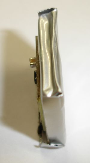 |  | ||
Finally the accu and board are installed on the main boards and soldered with power lines of the main board and with front contacts.
  |
The eagle data of the power management board can be downloaded form the section "Documentation".