BIOS, Communication, I/O and Perception Modules
BIOS represents the basic input/output system like those in PC. It interfaces the hardware to the rest of software system. Among sensor I/O functions, BIOS contains also motion and collision avoiding functions, supports remote control. Some functions of BIOS are implemented directly in assembler, so that BIOS is very compact (about 700 bytes).
I/O Services supports serial interface to PC (writing and reading). It is required only for service and test purposes so that at final compilation it can be
removed from the source (and so to save about 800 bytes of flash). When this module is included into active configuration, you will see starting message
Jasmine BIOS, v. xx
My ID x (x x x x)
My Role x (x x x)
indicating the start of autonomy cycle.
Comm module supports low-level local communication. It is based on the I/O sensor functions provided by BIOS. This module implements the PCM protocol
without submodulation for data exchange. There are basically two communication modes: sending without confirmation and with confirmation from a communication
partner. Generally, implementation of comm protocols requires a lot of memory and computational power. Therefore protocol without confirmation requires less
flash memory than protocol with confirmation (use it when appropriate).
Perception module is used for scanning and recognition/classification of data obtained from distance sensor. In BIOS v2.5 this module is subjected to serious
reworking so that a description of the feature vectors as well as usage of classified surface's geometry will be available only from the BIOS v2.6.
Like each microcontroller application, we also use status registers to control the robot. The most important are the following registers (the corresponding variables are globally available)
statusMain (type uint8_t 8 bit), this register contains the main status of the robot
statusComm1 (type uint8_t 8 bits) This register contains status of communication
statusComm2 (type uint8_t 8 bit) This register contains status of communication
Global variables are a bit expensive, bacause they requires more code, therefore we try to optimize using of these variables
BIOS functions:
Comm functions:
The robot can externally be controlled by IR-based remote control. This control system uses PCM (Pulse Code Modulation) to code the control bits. To make the IR signal resistant againts ambient light, the transmittion signal is submodulated by 36-40 kHz. The PCM-receiver (TSOP34836) decodes this submodulation (36kHz) and returns to external interrupt input of microcontroller a signal like shown below.
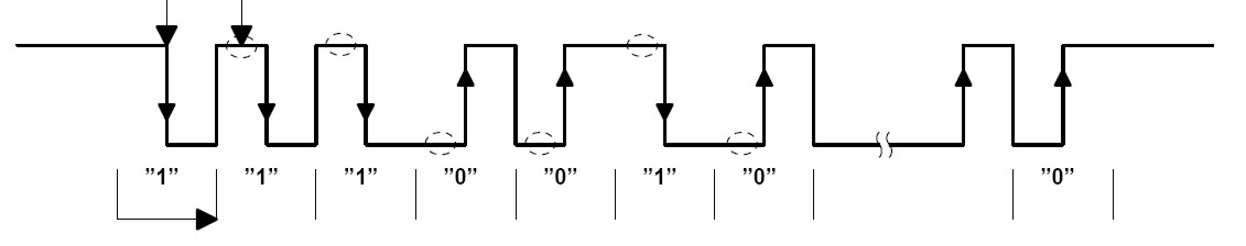
This signal can be decoded by looking on rising and faling edges and calculating a duration between these edges. The first part of the code shown below decode the duration of PCM pulses, whereas the second part of the code recognized commands.
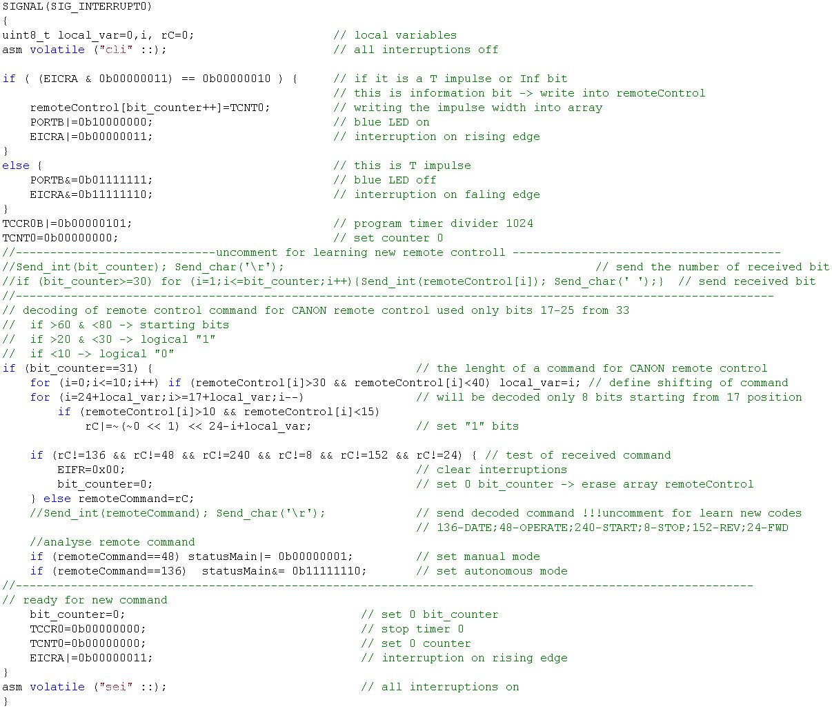
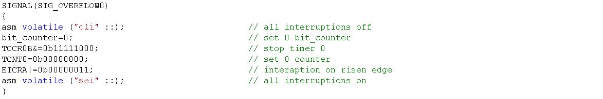
A part of RC command can be lost. For this reset timer anbd RC counter when is time is out (timer overflow).
How to learn new commands from remote control ?
I/O Services supports serial interface to PC (writing and reading). It is required only for service and test purposes so that at final compilation it can be
removed from the source (and so to save about 800 bytes of flash). When this module is included into active configuration, you will see starting message
Jasmine BIOS, v. xx
My ID x (x x x x)
My Role x (x x x)
indicating the start of autonomy cycle.
Comm module supports low-level local communication. It is based on the I/O sensor functions provided by BIOS. This module implements the PCM protocol
without submodulation for data exchange. There are basically two communication modes: sending without confirmation and with confirmation from a communication
partner. Generally, implementation of comm protocols requires a lot of memory and computational power. Therefore protocol without confirmation requires less
flash memory than protocol with confirmation (use it when appropriate).
Perception module is used for scanning and recognition/classification of data obtained from distance sensor. In BIOS v2.5 this module is subjected to serious
reworking so that a description of the feature vectors as well as usage of classified surface's geometry will be available only from the BIOS v2.6.
Like each microcontroller application, we also use status registers to control the robot. The most important are the following registers (the corresponding variables are globally available)
statusMain (type uint8_t 8 bit), this register contains the main status of the robot
| 0 bit- RC flag: | 0 - autonome mode; | 1 - manual mode via remote control | ||
| 1 bit- Obstacle flag: | 0 - no obstacles; | 1 - obstacle on the way | ||
| 2 bit- Motion flag: | 0 - no currect motion; | 1 - I'm moving now | ||
| 3 bit- Direction flag: | 0 - motion forwards; | 1 - motion backwards | ||
| 4 bit: Critical collision flag | 0 - there is still open; | 1 - no more motion | ||
| 5 bit: Read proximity flag: | 0 - don't read; | 1 - read | ||
| 6 bit: TWI synchronization flag: | 0 - process not finished | 1 - process is finished | ||
| 7 bit: Communication flag: | 0 - don't receive | 1 - listening for incomming messages | ||
statusComm1 (type uint8_t 8 bits) This register contains status of communication
| bits 0-4 | how many times an output message has to be sent; 64 times max | |||
| bits 5-7 | channel that receives the message | |||
statusComm2 (type uint8_t 8 bit) This register contains status of communication
| bits 0-6 | channels that should send the message | |||
| 7 bit- New message flag | 0 - no new input messages | 1 - there is a new input message | ||
Global variables are a bit expensive, bacause they requires more code, therefore we try to optimize using of these variables
| Type | Name | Description | ||
| uint8_t | remoteCommand | contains current command from remote control | ||
| uint8_t | myID | contains ID of the robot (EEPROM adress 0) | ||
| uint8_t | behavioralRole | contains a role in a swarm behavior (EEPROM adress 11) | ||
| 0 - normal swarm member | ||||
| 1 - scout (move and scan surfaces) | ||||
| 255 - empty | ||||
| uint8_t | localSensors[6] | this array contains current local sensor data | ||
| uint8_t | receivedTWICommand[6] | this array contains current commands received from TWI inteface | ||
| uint8_t | receivedTWICommIndex | contains current TWI commands index | ||
| uint8_t | receivMessage1 | the 1 wort of message obtained via communication | ||
| uint8_t | receivMessage2 | the 2 wort of message obtained via communication | ||
| uint8_t | sendMessage | the 1 wort of message to be sent | ||
| uint8_t | sendMessage2 | the 2 wort of message to be sent | ||
| uint8_t | statusPlan | contains the state (phase) that robot currently executing | ||
| uint8_t | statusPlanLast | contains the last state (phase) that robot executed | ||
BIOS functions:
| void Delay(uint8_t sleeptime) | provides delay in sleep mode in step of 64mks as the argument | |||
| void TimerStart(uint16_t IntTime) | provides timer software interruption into the state 14. Argument is 8mHz delay/1024 | |||
| void TimerStop(void) | stop timer software interruption | |||
| void EEPROM_write(unsigned int uiAdress, unsigned char ucData) | writes data into EEPROM | |||
| unsigned char EEPROM_read(unsigned int uiAdress) | reads data from EEPROM | |||
| uint8_t Read_sensor(uint8_t IR_channel) | Reads the 8 most significant bits of the AD conversion result (ADC input) | |||
| void JasminePorts(uint8_t IR_channel, uint8_t OnOff? ) | maps hardware ports in Jasmine sensors board to logical names | |||
| uint8_t Read_distance(uint8_t IR_channel) | returns the values of distance; it turns on the IR-emitters and then read ADC values | |||
| void Stop(void) | stop motion | |||
| void Move(unsigned char revDir, uint8_t steps) | direct motion, implementation in the BIOS of motion board | |||
| void Rotate(unsigned char Direct, uint8_t grad) | rotates the robot on 1 grad (255 max) LEFT and RIGHT, implementation in the BIOS of motion board | |||
| void LED_play(void) | playing of on-boards green, blue and red LEDs | |||
| void SendTWI(uint8_t adress, uint8_t data1, uint8_t data2) | sends two bytes trough TWI interface to adressed slave | |||
| void Initialize_Hardware(void) | performs initialization of ports, timers, interrupts and other hardware | |||
| void ReadProximity(void) | This performs proximity sensing | |||
| void CollisionAvoiding(void) | This performs collision avoiding | |||
Comm functions:
| void ReceiveMessages(void) | checks sensors and executes a communication protocol as a slave | |||
| void SendMessages(void) | sends a message using non-confirmation protocol | |||
| void SendMessagesC(void) | sends a message using protocol with confirmation | |||
The robot can externally be controlled by IR-based remote control. This control system uses PCM (Pulse Code Modulation) to code the control bits. To make the IR signal resistant againts ambient light, the transmittion signal is submodulated by 36-40 kHz. The PCM-receiver (TSOP34836) decodes this submodulation (36kHz) and returns to external interrupt input of microcontroller a signal like shown below.
This signal can be decoded by looking on rising and faling edges and calculating a duration between these edges. The first part of the code shown below decode the duration of PCM pulses, whereas the second part of the code recognized commands.
A part of RC command can be lost. For this reset timer anbd RC counter when is time is out (timer overflow).
How to learn new commands from remote control ?
- Choose such remote control that has 36 kHz submodulation, or select in universal remote control such a type that supports 36kHz.
- Uncomment lines that print received commands
- Choose bits that are definitely different in different commands (to decode the whole sequence has no sence until you will use only a few commands)
- Decode these bits in the way shown in source