Perception
Perception means recognition of object' properties like color, geometries and so on, whereas sensing (as e.g. proximity sensing) is more general capabilities to perceive the environment. In particular proximity sensing means obstacles detection.
Requirements.
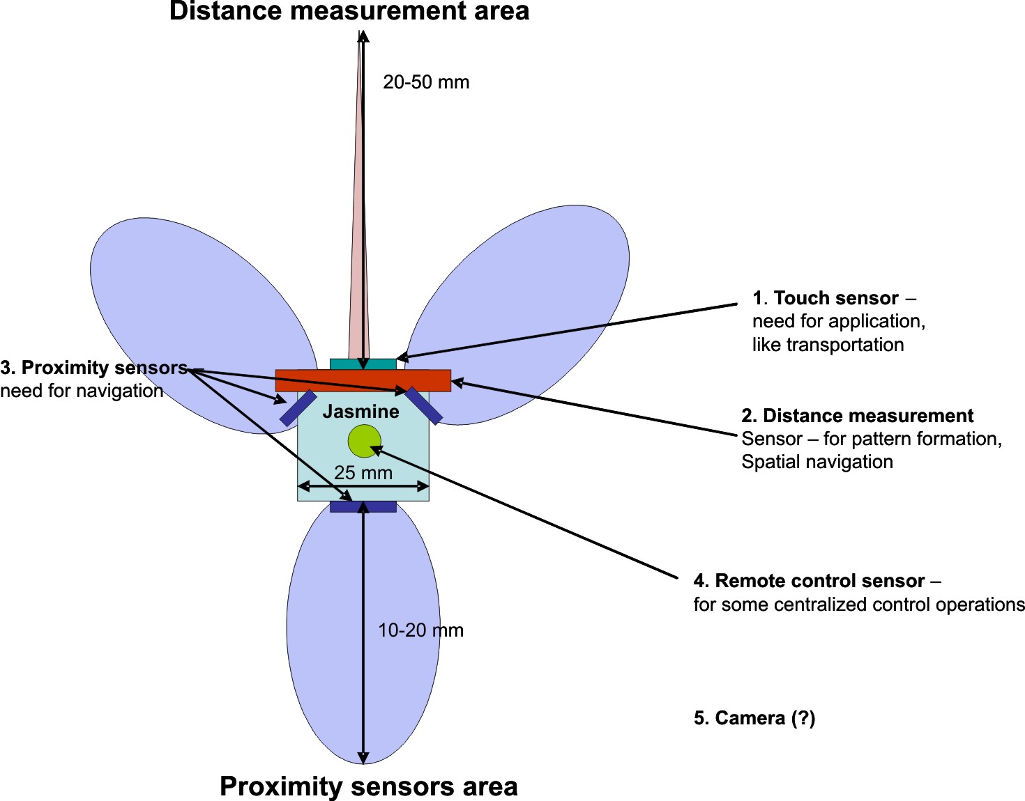
We expect to have proximity sensors in each of motion directions, that can estimate a distance to an obstacle as "far", "near" and "close". In the most scenarios imposed on a microrobotic swarm, robots have to perform different spatial operation, like building spatial formation, recognition of object's size and so on. For these tasks robots need a sensor that can measure the distance between itself and an obstacle. Measuring distances, geometrical features and visible size of surfaces are expected to be obtained. Based on them the robot can perform first the individual surface recognition, that can later be expanded on collective perception of large objects. We also expect that robots possess some sensor with PCM-filter for receiving a global modulated signal. Such a signal can be thought as of a remote control or a global information exchange between robots.
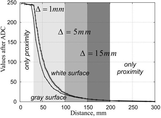
In the distance measurement the following parameters are the most important: max. measuring distance R_{max}, optimal recognition distance R_{rec}, opening angle of radiation/reflection ray alpha on R_{rec}, degradation of the IR radiation outsize opening angle, object and geometry resolution O_{res}, D_{res} in R_{rec}, dependency of reflection on color/slope of an object, as shown in figure below. We expect that distances are provided, at least, within R_c and a section of the IR radiation cone is less than
the size of robot's body.
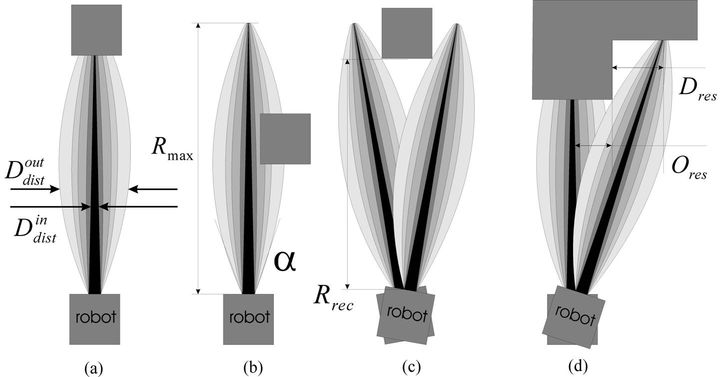
The general problem of distance and proximity sensing is so-called indiscernible distance. The sensor cannot differentiate whether the object is on the central line but in a large distance, or the real distance is smaller but the object is displaced from the central line. This problem still
remains open (can be solve when a robot undertakes several measurements in different directions). The similar problem appears when the object lies too far away or too closely to the sersor
Influence of ambient light.
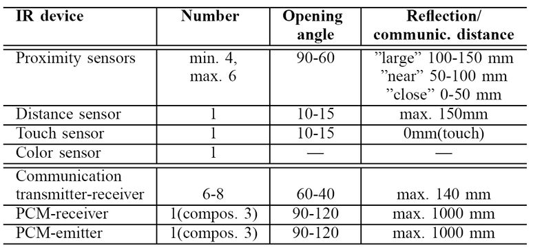
Ambient light represents generally very critical issue, because it can essentially distort or even completely break IR communication/sensing. The experiments are performed with luminescent lamp, filament lamp and daylight. We can estimate three different components of a distortion introduced by ambient light. The direct light saturates photoelectric transistor so that it gets "blind". Secondly, ambient light reduces sensor sensitivity, even when it does not fail directly on sensor. Finally, indirect ambient light reduces contrasts between object and background, so that results of measurement are no more reliable and reproducible. In Table below we collect some qualitative results.
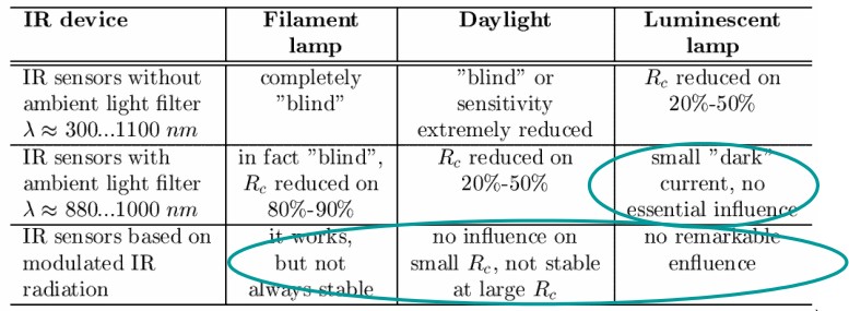
As followed from this table, a swarm has to be protected against a light of filament lamps. As far as possible, the direct daylight should be also avoided. Use of modulated light can essentially improve communication against ambient light, however this solution is not always feasible/acceptable. The filament lamps can be used as a global pheromone to control a swarm. When it is emitted simultaneously with luminescent light, the robot react more intensively on filament light. This effect can be utilized in many purposes, like finding the food source, navigation or even a quick message about some global event. This communication way does not require any additional sensors, however should used only as an exception, because it essentially distorts a regular communication.
Choosing of sensors
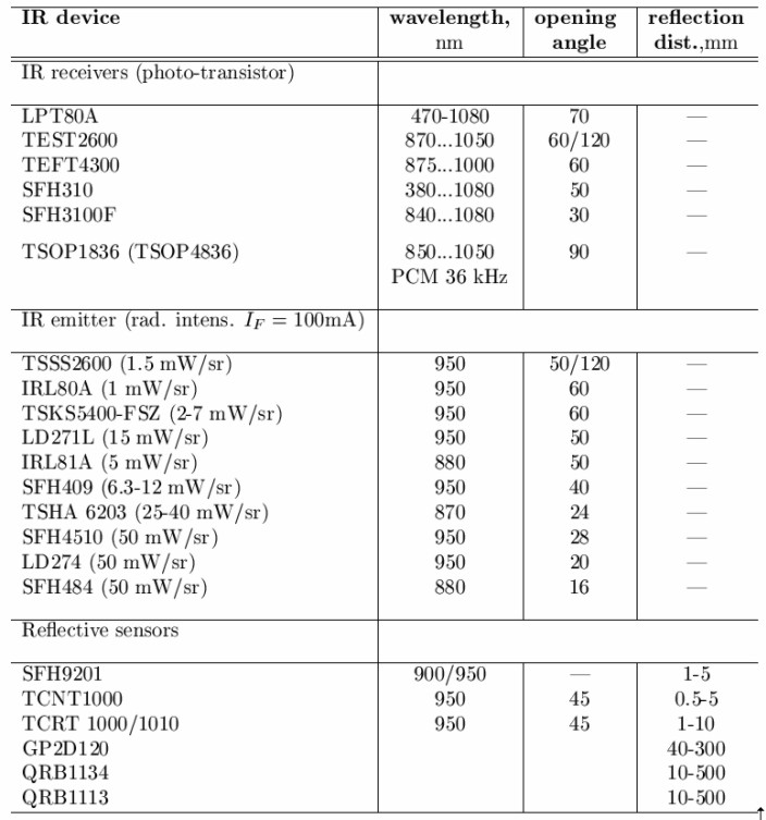
In experiments we firstly looked at IR devices datasheets of many manufacturer, like Vishay, Sharp, Osram, Siemens and others. The problem is that such an important parameter as the reflection/communication distance for separate optical diodes and transistor was not specified there. The suggested spectrally matched pairs diode/transistor usually do not satisfy the requirements on opening angle. Moreover, many desired IR devices are not available on micro-component market (or require large order). Finally, we decided to purchase all suitable and available IR devices (they are not expensive, usual price is of cents) and to perform experiments with them. In the purchasing we select different groups of sensors so that results of experiments can be applied not only to the chosen sensor, but also to the whole group of sensors. In experiments we investigated the following parameters:
- Influence of ambient light on communication/reflextion;
- Reflection distance/reflection angle;
- Communication distance/communication angle;
- Communication speed;
- Size and energy consumption.
The current I_F of IR emitters was limited to 20 mA, that corresponds to I/O ports of the microcontroller. Experiments have been done by measuring a voltage V_o on the emitter of phototransistor. The emitter resistance are chosen so that at a maximal reflection the max. voltage equals V_o approx 5 V. We purchased also only such devices that provide analog output signal, therefore such popular sensors as IS471F or Sharp's GP2Dxxx with binary output are not considered. In Figures below we show some tested sensors (from over 30 pairs).
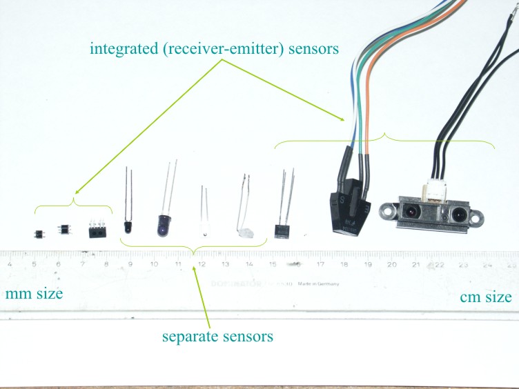
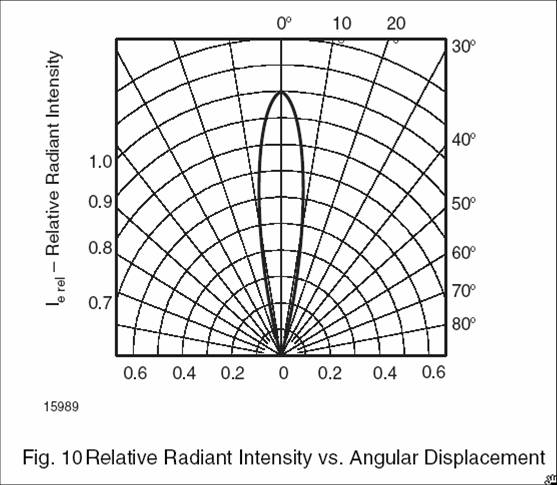
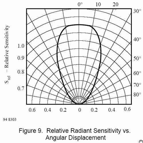
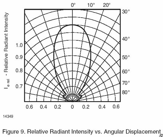
Analyzing the results of experiments, we came to the conclusion that the integrated sensors are not really suitable for this application, although they have good coverage in 60° sector. The measured distances is only of 40-50 mm (on the brink of recognizability), and communication radius R_c is about 60-70 mm (also on the brink of recognizability). The IR emitters with opening angle of 40 and less degree do not provide a good coverage in 60° sector. From the tested IR emitters only one TSKS5400-FSZ demonstrated acceptable coverage that can be approximated in the algorithmic way. The sensor QRD1113 shows really good results, however it was extremely sensitive even to the luminescent light, so that its further calibration represents essential difficulties (receiver and emitter should be optically isolated so that to provide only 60° opening angle, they can perceive and send till 80-90°). Finally we choose TSAL6100 as long-range emitter, and TSKS5400-FSZ and TEFT4300 as sersors, their radiation diagrams are shown in figure below.
 |
 |  |
Choosing of color sensors
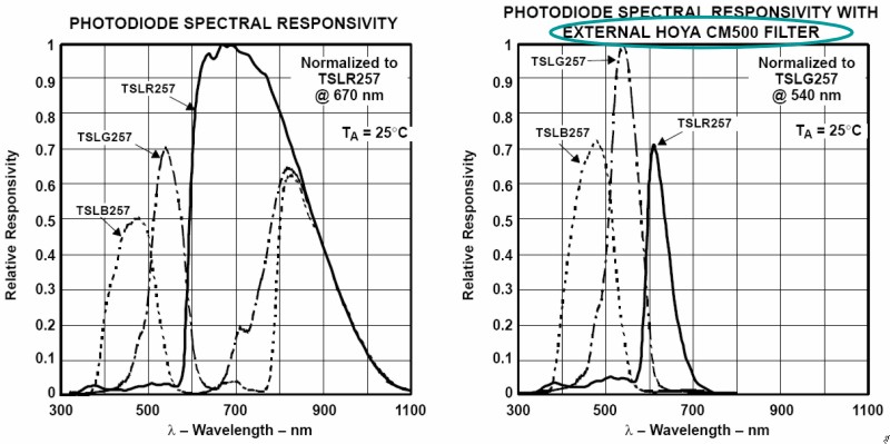
For color sensing we tested TSLB257, TSLG257, TSLR257 color-light-to-voltage convertors. The main problem we encountered is that the color perception as well as a communication by color LEDs cannot be done in a presence of any ambient light. The sensor cannot differentiate whether the light comes from color emitter (or reflected light from colored object) or it is an ambient light. This problem is remained unsolved (when somebody knows a good color sensor -> please post a replay).
Experiments
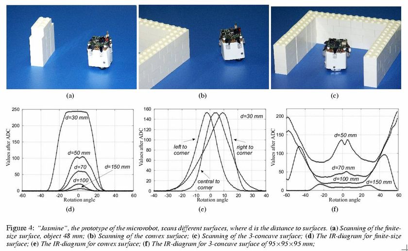
The principle of perception is the following. As soon as a robot detects (by means of proximity sensors) an obstacle in front of itself, it stops and rotates on the angle of 60 degree left. After that it switches on the high power IR emitter and scans the obstacle by rotating 120° right. During this scanning it writes the values of distances each 1 degree into an integer array. In this way 120 values describe a visible geometry of the encountered obstacle. In figure below we demonstrate some geometries of obstacles and the scanned values of distances.
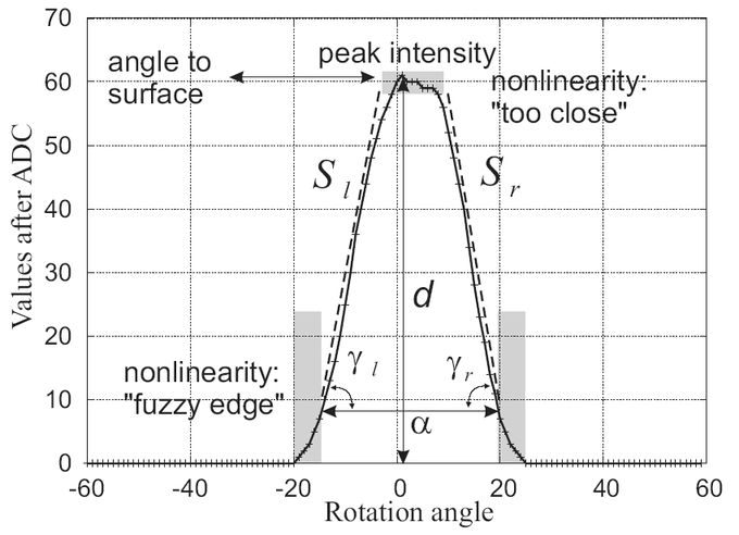
For surfaces recognition we can use the following features:
- The angel alpha, which represents the scanning angle between the first visible edge and the last visible edge of the surface;
-
The peak intensity of the diagram I_max. This corresponds to the maximal intensity of reflecting light and, in turn, to the minimal distance d between the surface and the microrobot. For the most types of surfaces (beside convex corners) this minimal distance is measured as a perpendicular to a surface. This feature allows calculating the visible size of a surface by using trigonometric relation;
-
The left and right slopes, denoted as gamma_l and gamma_r. We concluded that the slope is also useful for identifying the type of the surface (unlimited, big, small). They are calculated as slopes of the approximation lines S_l, S_r. The slope denotes also the "degree of a distance decreasing" and enable us to identify so-called "convex surfaces" that cannot be recognized in the trigonometrical way;
-
The position of the "centrum" of the IR diagram P_imax in relation to the rotation angel ("0" point). Displacement of the centrum points to a slope between the from of robot and surface. In this way we can identify a global orientation of the microrobot.